


Indexing in Milling Machine
In this article, you can learn indexing in milling machine and methods of indexing.
What is indexing in milling machine?
Milling operations sometimes, require the rotation of job correct to fractions of minutes, for each groove, slot etc., to be cut evenly on the job surface. The accuracy of spacing of teeth is very important particularly when the work is of precision character e.g., gear teeth, shafts, cutter teeth etc.
The operation of rotating the job through a required angle between two successive cuts is termed as indexing. This is accomplished with the help of a milling attachment known as Indexing head, which is an accessory to the milling machine. It helps to divide the job periphery into a number of equal divisions, i.e., square, hexagonal octagonal, etc.
Indexing Head Definition
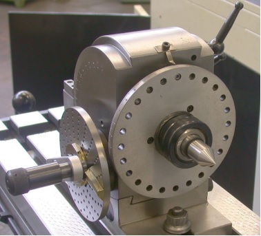
An indexing head, also known as a dividing head or spiral head, is a specialized tool that allows a workpiece to be circularly indexed; that is, easily and precisely rotated to preset angles or circular divisions. Indexing heads are usually used on the tables of milling machines, but may be used on many other machine tools including drill presses, grinders, and boring machines. Common jobs for a dividing head include machining the flutes of a milling cutter, cutting the teeth of a gear, milling curved slots, or drilling a bolt hole circle around the circumference of a part.
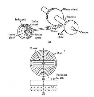
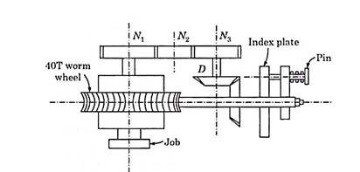
In dividing head, the first requirement is met by an index-crank and the second by the index plate. The index-plate has a number of holes arranged concentrically, so that each circle has a number of holes equally spaced.
The crank has an arrangement in connection with the plunger-pin, which can slide through the slot and the crank is pivoted at the centre of a disc. This crank can be rotated about the axis and the plunger can be fixed at any desired hole.
The rotation of crank is transmitted through a gear to the job, so that the number of complete revolutions will result in certain revolutions of the job. The ratio of crank and the shaft on which job is mounted is 40 : 1, i.e., when the index plate makes 40 revolutions, the job makes one revolution.
For quick-placing of plunger and in order to avoid the counting of holes, fixed arms (sectors) are provided which can be set apart at any number of holes desired.
5 methods of Indexing
1. Direct Indexing
The direct indexing is also called Rapid indexing, and it is used when a large number of pieces are indexed with a small division.
This operation can be done in both plain and universal dividing head. When using the Universal head, the worm and worm wheel are first disengaged.
The required number of divisions on the work is obtained by means of the rapid index plate which is fitted at the front end of the spindle nose. The plate has 24 equally spaced holes.
The spring-loaded pin can be pushed into any of the holes to lock the spindle with the frame.
For indexing, the pin is taken out first and then spindle is rotated by hand, and after the required position is reached it is again locked by the pin.
When the plate is turned through the required part of the revolution, the dividing head spindle and the work are also turned through the same part of the revolution.
With a Rapid indexing plate of 20 holes, it is possible to divide the work into an equal division of 2,3,4,6,8,12 and 24 parts which are all the factors of 24.
To find the index movement, find the total number of holes in the direct index plate by the number of divisions required in the work, If N is the number of divisions required on the work then,
[Number of holes be removed= 24/N]
2. Simple or Plain Indexing
Simple indexing is also called as 9 indexing. It is more accurate and has a large range of indexing than rapid indexing.
For indexing, the dividing head spindle is turned by the index crank.
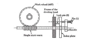
The worm shaft carrying the crank has a single-threaded worm which meshes with worm gear having 40 teeth, 40 turns of the crank are necessary to rotate the index head spindle through one revolution.
Therefore, one complete turn of the index crank will cause the worm wheel to make 1/40 of a revolution. To facilitate indexing to the fraction of a turn, an Index plate is used to cover practically all numbers.
The Index plate with a circle of holes manufactured by the brown and sharp company are:
Plate No 1: 15,16,17,18,19,20
Plate No 2: 21,23,27,29,31,33
Plate No 3: 37,39,41,43,47,49
To find the index crank movement, divided 40 by number of division required on the work,
[Index crank movement= 40/N]
Where N is the number of divisions required on the work.
3. Angular Indexing
The angular indexing is the Process of dividing the periphery of work in angular measurements.
There are 360 degrees in a circle, and then the index crank is rotated by 40 number of revolution,
and the spindle rotates through 1 complete Revolution or by 360 degrees, one complete turn off the crank will cause the spindle and the work to rotate through 360/40=9 degrees.
Therefore in order to turn work through a required angle, the number of turns required for index crank can be calculated by the number ‘9’.
Angular displacement is expressed in minutes then the terms of the index crank can be calculated by dividing the angle by 540.
If it is expressed in seconds then it is divided by 32400.
When a result is a whole number, the index crank is rotated through the full calculated number.
If the result is a fraction and a whole number,
the part of the revolution of the crank after turning the whole number is calculated by multiplying is suitable for numbers to the numerator and denominator of the fraction, defecation to make the denominator of the fraction is equal to the number of holes in the index plate circle and the now numerator number for holes to be moved by the index Crank.
The index crank Movement= Angular displacement of work, in degrees /9
= in minutes / 540
= in seconds / 32400
4. Compound Indexing
In Compound indexing, there are two separate movements of the index crank in two different hole circles of one index plate to get the crank movement.
The index plate is held stationary by Lock pin heed which engages with one of the whole circle of the index place from the back.
For indexing first, the crankpin is rotated by the required number of the spaces in one of the holes of the circle of the index plate and then the pin is engaged with the plate.
The second index movement is done by removing the real lock pin and the rotating the plate together with the index crank forward or backward through the calculated number of spaces of another hole circle, and the lock pin is engaged.
5. Differential Indexing
Available number of index plates with different hole circles, sometimes confine the range of plain indexing. In such cases, differential indexing is found to be more suitable. Between the indexing plate and spindle of dividing head, a certain set of the gears is incorporated extra. Dividing heads are provided with such standard set of gears.
During the differential indexing, the index-plate is unlocked and connected to a train of gears which receive their motion from the worm gear spindle. As the handle is turned, the index plate also turns, but at a different rate and perhaps in the opposite direction. Differential indexing makes it possible to rotate the work by any fraction of revolution with the usual index plates furnished with the equipment.
For making the necessary calculations and to find the change of gears to be placed between the spindle and the worm shaft, use the following relation:
where N is the number of divisions to be indexed and n is a number slightly greater or less than N. The relation given by equation will give a gear ratio to be placed on spindle (Driver) and the work shaft (Driven). The arrangement of gears can be in the form of simple wheel train or compound wheel train or compound wheel train depending upon the suitability and requirements.
The difference of N and n causes the index plate to rotate itself in a proper direction relative to crank. If (n — N) is positive, the index plate will rotate in the direction in which crank is rotated and if (n — N) is negative, it will rotate in opposite direction to that of crank.