


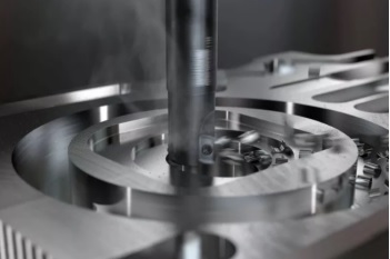
Summary of experience: How to Mill Different Materials?
01 Steel Milling
The machinability of steel varies with alloying elements, heat treatment and manufacturing processes (forging, casting, etc.). When processing soft low-carbon steel, the main problem is the formation of built-up edge and the formation of burrs on the workpiece. In order to avoid chipping when machining harder steels, the relative position of the milling cutter and the workpiece will become more important.
Suggestion:
When milling steel parts, optimize the position of the milling cutter to avoid the appearance of thick chips when the tool is retracted. Make sure to consider dry cutting without the use of cutting fluid, especially in the rough machining process.
02 Stainless Steel Milling
Stainless steel can be classified into ferritic/martensitic stainless steel, austenitic stainless steel and duplex (austenitic/ferritic) stainless steel, each type has its own milling recommendations.
1. Classification of ferritic/martensitic stainless steel milling materials: P5.x
The machinability of ferritic stainless steel is similar to that of low-alloy steel, so steel milling recommendations can be used.
Martensitic stainless steel has higher work hardening properties and requires very high cutting force when cutting. Use the correct tool path and arc cutting method to obtain the best results, and use a higher cutting speed Vc to overcome the work hardening effect. Higher cutting speeds, tougher materials and enhanced cutting edges can ensure higher safety.
2. Classification of austenitic and duplex stainless steel milling materials: M1.x, M2.x and M3.x
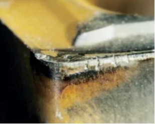
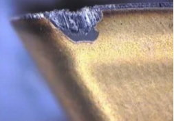
The main wear criteria for milling austenitic stainless steel and duplex stainless steel are cutting edge chipping due to hot cracking, groove wear and built-up edge/bonding. For parts, burr formation and surface quality issues are the main issues.
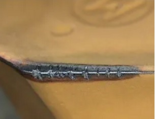
Hot crack
Insert cutting edge chipping
Burr formation and poor surface quality
Roughing suggestion:
Use high cutting speed (Vc=150-250m/min) to avoid built-up edge and dry cutting without using cutting fluid to minimize the problem of hot cracks.
Finishing suggestion:
1. In order to improve the surface quality, sometimes it is necessary to use cutting fluid or preferably oil mist lubrication/minimum lubrication. There are fewer hot cracking problems during finishing, because the heat generated in the cutting area is lower.
2. When using cermet materials, a sufficiently good surface quality can be obtained without using cutting fluid.
3. If the feed fz is too low, the cutting edge may cut in the deformation hardened zone and cause more severe wear of the insert.
03 Cast Iron Milling
1. Gray cast iron material classification: K2.x
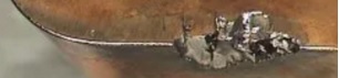
The main wear criteria for gray cast iron milling are abrasive/flank wear and hot cracks. For parts, chipping and surface quality problems are the main problems.
Typical blade wear
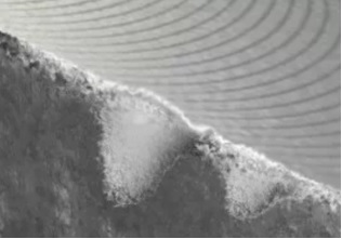
Workpiece chipping
Roughing suggestion:
1) It is best to dry cutting without using cutting fluid to minimize the problem of hot cracks. Use thick-coated carbide blades.
2) If there is a problem of workpiece chipping:
*Check the flank wear
*Reduce feed fz to reduce chip thickness
*Use a groove with a larger positive rake angle
*It is better to use 65°/60°/45° milling cutter
3) If cutting fluid must be used to avoid dust, etc., choose wet milling material.
4) Coated cemented carbide is always the first choice, but ceramic materials can also be used. Please note that the cutting speed Vc should be very high, 800-1000m/min. The formation of burrs on the workpiece limits the cutting speed. Do not use cutting fluid.
Finishing suggestion:
1) Use thin-coated carbide blades or, alternatively, use uncoated carbide blades.
2) CBN material can be used for high-speed finishing. Do not use cutting fluid.
2. Classification of ductile iron materials: K3.x
1) The machinability of ferritic ductile iron and ferritic/pearlite ductile iron is very similar to that of low alloy steel. Therefore, the milling recommendations provided for steel materials should be used when selecting tools, insert geometries and materials.
2) Pearlitic ductile iron is more abrasive, so it is recommended to use cast iron.
3) The use of PVD coating material and wet cutting can ensure the best processing ability.
3. Compacted graphite iron (CGI) material classification: K4.x
The pearlite content is less than 90%. The type of CGI most commonly used for milling processing usually has a pearlite structure of about 80%. Typical parts are engine cylinder block, cylinder head and exhaust manifold.
The recommendations for milling cutters are the same as when machining gray cast iron; however, insert geometries with sharper cutting edges and larger positive rake angles should be selected to minimize burrs formed on the parts. Arc milling may be a very good alternative to traditional CGI cylinder boring.
4. Austempered ductile iron (ADI) material classification: K5.x
Rough machining is usually performed in an unhardened state and is comparable to high-alloy steel milling. However, the processing object of the finishing process is a hardened material with very high abrasiveness. This is comparable to ISO H hardened steel milling. Materials with higher resistance to abrasive wear are preferred. Compared with NCI, the tool life when machining ADI is reduced to about 40%, and the cutting force is increased by about 40%.
04 Non-ferrous Metal Material Milling
Non-ferrous metal materials include not only aluminum alloys, but also magnesium, copper and zinc-based alloys. Machinability is mainly due to the difference in silicon content. Hypoeutectic aluminum-silicon alloy is the most common type, with a silicon content of less than 13%.
1. Classification of aluminum alloy materials with silicon content less than 13%: N1.1-3
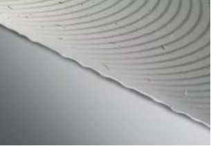
The main wear criterion is built-up edge/bonding on the cutting edge, which leads to burr formation and surface quality problems. In order to avoid leaving scratches on the surface of the part, good chip formation and chip removal are essential.
Suggestion:
1) The use of PCD tipped inserts with sharp polished cutting edges can ensure good chip breaking ability and prevent build-up edge.
2) Choose a positive rake insert geometry with sharp cutting edges.
3) Unlike most other milling applications, cutting fluid should always be used when machining aluminum alloys to avoid material sticking to the blade cutting edge and improve surface quality.
*Silicon content <8%: use a cutting fluid with a concentration of 5%
*Silicon content <8-12%: Use cutting fluid with a concentration of 10%
*Silicon content> 12%: Use a cutting fluid with a concentration of 15%
4) Higher cutting speeds generally improve performance without negatively affecting tool life.
5) The recommended value of hex is 0.10-0.20 mm (0.0039-0.0079 inch). If the value is too small, it will cause burr formation.
6) Due to the high table feed, a machine tool with "pre-reading" function should be used to avoid dimensional errors.
7) Tool life is always limited by burr formation or surface quality of parts. Blade wear is difficult to use as a tool life criterion.
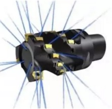
05 High Temperature Alloys and Titanium Alloys
Milling of high-temperature alloys and titanium usually requires high-rigidity, high-power and high-torque machine tools to run at low speeds. Groove wear and cutting edge chipping are the most common types of wear. The high heat generated will limit the cutting speed.
Suggestion:
Use round blade milling cutters as much as possible to increase the chip thinning effect.
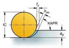
The use of round blade milling cutters minimizes groove wear
When the cutting depth is less than 5mm, the entering angle should be less than 45°. In practice, it is recommended to use a positive round blade.
The radial and axial accuracy of the milling cutter is a necessary condition to maintain a constant load per tooth, a smooth process, and to prevent premature damage to a single blade.
The cutting edge should always have a positive rake angle geometry and an optimized cutting edge rounding treatment to prevent chips from sticking to the cutting edge when the tool is retracted.
The number of cutting teeth actually involved in cutting during the milling process should be as large as possible. Under stable conditions, this will achieve ideal productivity. Use ultra-close pitch milling cutter.
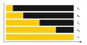
Yellow: Tool life
Black: Tool life decreases with the increase of cutting parameters
Changes will have different effects on tool life. Cutting speed Vc has the greatest impact, followed by ae and so on.
Cutting fluid/coolant
Unlike most other materials when milling, it is always recommended to use coolant to help chip evacuation to control the heat at the cutting edge and prevent secondary chip cutting. The first choice is always the internal cooling high pressure coolant (70 bar) applied through the spindle/tool, rather than the external cooling and low pressure coolant.
Exception: When milling with ceramic inserts, cutting fluid should not be used due to thermal shock.
When using cemented carbide blades, internal cooling will bring benefits.
Blade/tool wear
The most common causes of tool breakage and poor surface quality are groove wear, excessive flank wear, and chipped edge lines.
The best solution is to frequently index the cutting edge to ensure a reliable machining process. The flank wear of the cutting edge should not exceed 0.2mm (for milling cutters with an entering angle of 90°), or the maximum should not exceed 0.3mm (for round inserts).
Typical blade wear
Ceramic blade milling cutter for rough machining of high temperature alloy
The speed of ceramic milling is usually 20-30 times that of cemented carbide milling, although the feed rate is lower (about 0.1mm/z), which will result in a substantial increase in productivity. Due to the use of interrupted cutting, the temperature of the milling process is much lower than that of turning. Therefore, the cutting speed of 700-1000m/min is used for milling, compared to only 200-300m/min for turning.
Suggestion:
1) Mainly use round blades to ensure a small entering angle and prevent groove wear.
2) Do not use cutting fluid/coolant.
3) Do not use ceramic blades when processing titanium alloys.
4) 4 Ceramics will have a negative impact on surface integrity and other indicators. Therefore, do not use ceramic blades when the shape of the finished part is about to be processed.
5) The maximum flank wear when machining high temperature alloys with ceramic inserts is 0.6mm.
06 Hardened Steel Milling
This group includes quenched and tempered steel with hardness greater than 45-65HRC. Typical parts for milling include stamping molds, plastic molds, forging molds, die-casting molds, etc. Blade abrasive/flank wear and workpiece chipping are the main problems.
Suggestion:
1) Use a positive rake insert geometry with sharp cutting edges. This will reduce the cutting force and produce a smoother cutting action.
2) Dry cutting, avoid using cutting fluid.
3) Cycloid milling is an appropriate method, which can achieve high table feed and low cutting force at the same time, so that the cutting edge and workpiece can be kept at low temperature, which is beneficial for productivity, tool life and part tolerances .
4) In face milling, a light-cutting processing strategy should also be adopted, that is, while maintaining a small depth of cut ae and ap. Use ultra-close pitch milling cutter and relatively high cutting speed.