Turning VS Milling
Both turning and milling are material removal processes, which can create a variety of features on a part by cutting away the unwanted material. Although both turning and milling follows the principles of subtractive manufacturing, their areas of application are different. Which one should I use for my project? Turning or milling? You can get an answer from this article. This article focuses on the following points.
Similarities between turning and milling
Differences between turning and milling
Advantages and disadvantages of milling and turning
Turning or Milling, which process is best for your project?
Similarities between turning and milling
1.Both turning and milling are conventional machining processes. Such processes utilize a specially designed cutting tool that physically compresses a thin layer of workpiece material to gradually shear it off in the form of a solid chip.
2.Both turning and milling follow subtractive manufacturing approach. Here layer by layer material is removed from a solid 3-D block to obtain the intended product. On the contrary, the additive manufacturing approach follows the concept of the addition of a thin layer of material one over another to build a solid 3-D block.
3.Both turning and milling processes employ a solid cutting tool to shear off material from the workpiece; however, the shape and features of the cutters for these two processes vary widely. Chip formation is inherent in both the cases. In fact, it is fundamental to every conventional machining process.
4.Both processes can produce reasonably good surface finish; however, it depends on several other factors including cutting velocity, feed rate, depth of cut, tool geometry, cutting environment, etc.
5.Heat generation is inherent in both the processes. Consequent effects of high cutting temperatures are also similar for both the operations. Cutting fluid can be applied in both the processes.
Differences between turning and milling
Equipment
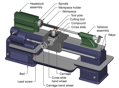
1.Turning machines, typically referred to as lathes, can be found in a variety of sizes and designs. While most lathes are horizontal turning machines, vertical machines are sometimes used, typically for large diameter workpieces. Turning machines can also be classified by the type of control that is offered. A manual lathe requires the operator to control the motion of the cutting tool during the turning operation. Turning machines are also able to be computer-controlled, in which case they are referred to as a computer numerical control (CNC) lathe. CNC lathes rotate the workpiece and move the cutting tool based on commands that are preprogrammed and offer very high precision. In this variety of turning machines, the main components that enable the workpiece to be rotated and the cutting tool to be fed into the workpiece remain the same. These components include the following:

Headstock assembly - The headstock assembly is the front section of the machine that is attached to the bed. This assembly contains the motor and drive system which powers the spindle. The spindle supports and rotates the workpiece, which is secured in a workpiece holder or fixture, such as a chuck or collet.
Tailstock assembly - The tailstock assembly is the rear section of the machine that is attached to the bed. The purpose of this assembly is to support the other end of the workpiece and allow it to rotate, as it's driven by the spindle. For some turning operations, the workpiece is not supported by the tailstock so that material can be removed from the end.
Carriage - The carriage is a platform that slides alongside the workpiece, allowing the cutting tool to cut away material as it moves. The carriage rests on tracks that lay on the bed, called "ways", and is advanced by a lead screw powered by a motor or handwheel.
Cross slide - The cross slide is attached to the top of the carriage and allows the tool to move towards or away from the workpiece, changing the depth of cut. As with the carriage, the cross slide is powered by a motor or handwheel.
Compound - The compound is attached on top of the cross slide and supports the cutting tool. The cutting tool is secured in a tool post which is fixed to the compound. The compound can rotate to alter the angle of the cutting tool relative to the workpiece.
Turret - Some machines include a turret, which can hold multiple cutting tools and rotates the required tool into position to cut the workpiece. The turret also moves along the workpiece, feeding the cutting tool into the material. While most cutting tools are stationary in the turret, live tooling can also be used. Live tooling refers to powered tools, such as mills, drills, reamers, and taps, which rotate and cut the workpiece.
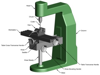
2.Milling machines can be found in a variety of sizes and designs, yet they still possess the same main components that enable the workpiece to be moved in three directions relative to the tool. These components include the following:

Table - The workpiece that will be milled is mounted onto a platform called the table, which typically has "T" shaped slots along its surface. The workpiece may be secured in a fixture called a vise, which is secured into the T-slots, or the workpiece can be clamped directly into these slots. The table provides the horizontal motion of the workpiece in the X-direction by sliding along a platform beneath it, called the saddle.
Saddle - The saddle is the platform that supports the table and allows its longitudinal motion. The saddle is also able to move and provides the horizontal motion of the workpiece in the Y-direction by sliding transversely along another platform called the knee.
Knee - The knee is the platform that supports the saddle and the table. In most milling machines, sometimes called column and knee milling machines, the knee provides the vertical motion (Z direction) of the workpiece. The knee can move vertically along the column, thus moving the workpiece vertically while the cutter remains stationary above it. However, in a fixed bed machine, the knee is fixed while the cutter moves vertically in order to cut the workpiece.
The above components of the milling machine can be oriented either vertically or horizontally, creating two very distinct forms of milling machine. A horizontal milling machine uses a cutter that is mounted on a horizontal shaft, called an arbor, above the workpiece. For this reason, horizontal milling is sometimes referred to as arbor milling. The arbor is supported on one side by an overarm, which is connected to the column, and on the other side by the spindle. The spindle is driven by a motor and therefore rotates the arbor. During milling, the cutter rotates along a horizontal axis and the side of the cutter removes material from the workpiece. A vertical milling machine, on the other hand, orients the cutter vertically. The cutter is secured inside a piece called a collet, which is then attached to the vertically oriented spindle. The spindle is located inside the milling head, which is attached to the column. The milling operations performed on a vertical milling machine remove material by using both the bottom and sides of the cutter.
Milling machines can also be classified by the type of control that is used. A manual milling machine requires the operator to control the motion of the cutter during the milling operation. The operator adjusts the position of the cutter by using hand cranks that move the table, saddle, and knee. Milling machines are also able to be computer-controlled, in which case they are referred to as a computer numerical control (CNC) milling machine. CNC milling machines move the workpiece and cutter based on commands that are preprogrammed and offer very high precision. The programs that are written are often called G-codes or NC-codes. Many CNC milling machines also contain another axis of motion besides the standard X-Y-Z motion. The angle of the spindle and cutter can be changed, allowing for even more complex shapes to be milled.
Tooling
1.The tooling that is required for turning is typically a sharp single-point cutting tool that is either a single piece of metal or a long rectangular tool shank with a sharp insert attached to the end. These inserts can vary in size and shape, but are typically a square, triangle, or diamond-shaped piece. These cutting tools are inserted into the turret or a tool holder and fed into the rotating workpiece to cut away material. These single point-cutting tools are available in a variety of shapes that allow for the formation of different features. Some common types of tools are as follows:
*Style B - 15 degree lead-angle turning tools
*Style C - 0 degree square nose tools
*Style D - 80 degree included angle pointed-nose tools
*Style E - 60 degree included angle pointed-nose tools
*Cutoff tools
*Form tools
The above tools are often specified as being right or left-handed, which indicates in which direction they move along the workpiece while making a cut.
Live tooling can also be used for turning, which includes the use of mills, drills, reamers, and taps. These are cylindrical multi-point cutting tools that have sharp teeth spaced around the exterior. The spaces between the teeth are called flutes and allow the material chips to move away from the workpiece. The teeth may be straight along the side of the cutter, but are more commonly arranged in a helix. The helix angle reduces the load on the teeth by distributing the forces. Also, the number of teeth on a cutter varies. A larger number of teeth will provide a better surface finish. The cutter teeth cover only a portion of the tool, while the remaining length is a smooth surface, called the shank. The shank is the section of the cutter that is secured inside the tool holder.
All cutting tools that are used in turning can be found in a variety of materials, which will determine the tool's properties and the workpiece materials for which it is best suited. These properties include the tool's hardness, toughness, and resistance to wear. The most common tool materials that are used include the following:
*High-speed steel (HSS)
*Carbide
*Carbon steel
*Cobalt high-speed steel
The material of the tool is chosen based upon a number of factors, including the material of the workpiece, cost, and tool life. Tool life is an important characteristic that is considered when selecting a tool, as it greatly affects the manufacturing costs. A short tool life will not only require additional tools to be purchased, but will also require time to change the tool each time it becomes too worn.
2.The tooling that is required for milling is a sharp cutter that will be rotated by the spindle. The cutter is a cylindrical tool with sharp teeth spaced around the exterior. The spaces between the teeth are called flutes and allow the material chips to move away from the workpiece. The teeth may be straight along the side of the cutter, but are more commonly arranged in a helix. The helix angle reduces the load on the teeth by distributing the forces. Also, the number of teeth on a cutter varies. A larger number of teeth will provide a better surface finish. The cutters that can be used for milling operations are highly diverse, thus allowing for the formation of a variety of features. While these cutters differ greatly in diameter, length, and by the shape of the cut they will form, they also differ based upon their orientation, whether they will be used horizontally or vertically.
A cutter that will be used in a horizontal milling machine will have the teeth extend along the entire length of the tool. The interior of the tool will be hollow so that it can be mounted onto the arbor. With this basic form, there are still many different types of cutters that can be used in horizontal milling, including those listed below.
*Plane (helical) mill
*Form relieved mill
*Staggered tooth mill
*Double angle mill
Another operation known as a straddle milling is also possible with a horizontal milling machine. This form of milling refers to the use of multiple cutters attached to the arbor and used simultaneously. Straddle milling can be used to form a complex feature with a single cut.
For vertical milling machines, the cutters take a very different form. The cutter teeth cover only a portion of the tool, while the remaining length is a smooth surface, called the shank. The shank is the section of the cutter that is secured inside the collet, for attachment to the spindle. Also, many vertical cutters are designed to cut using both the sides and the bottom of the cutter. Listed below are several common vertical cutters.
*Flat end mill
*Ball end mill
*Chamfer mill
*Face mill
*Twist drill
*Reamer
*Tap
All cutters that are used in milling can be found in a variety of materials, which will determine the cutter's properties and the workpiece materials for which it is best suited. These properties include the cutter's hardness, toughness, and resistance to wear. The most common cutter materials that are used include the following:
*High-speed steel (HSS)
*Carbide
*Carbon steel
*Cobalt high speed steel
The material of the cutter is chosen based upon a number of factors, including the material of the workpiece, cost, and tool life. Tool life is an important characteristic that is considered when selecting a cutter, as it greatly affects the manufacturing costs. A short tool life will not only require additional tools to be purchased, but will also require time to change the tool each time it becomes too worn. The cutters listed above often have the teeth coated with a different material to provide additional wear resistance, thus extending the life of the tool. Tool wear can also be reduced by spraying a lubricant and/or coolant on the cutter and workpiece during milling. This fluid is used to reduce the temperature of the cutter, which can get quite hot during milling, and reduce the friction at the interface between the cutter and the workpiece, thus increasing the tool life. Also, by spraying a fluid during milling, higher feed rates can be used, the surface finish can be improved, and the material chips can be pushed away. Typical cutting fluids include mineral, synthetic, and water-soluble oils.
Materials
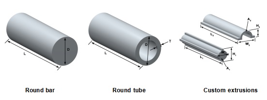
In turning, the raw form of the material is a piece of stock from which the workpieces are cut. This stock is available in a variety of shapes such as solid cylindrical bars and hollow tubes. Custom extrusions or existing parts such as castings or forgings are also sometimes used.

Turning can be performed on a variety of materials, including most metals and plastics. Common materials that are used in turning include the following:
*Aluminum
*Brass
*Magnesium
*Nickel
*Steel
*Thermoset plastics
*Titanium
*Zinc
When selecting a material, several factors must be considered, including the cost, strength, resistance to wear, and machinability. The machinability of a material is difficult to quantify, but can be said to possess the following characteristics:
*Results in a good surface finish
*Promotes long tool life
*Requires low force and power to turn
*Provides easy collection of chips
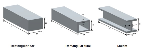
2.In milling, the raw form of the material is a piece of stock from which the workpieces are cut. This stock is available in a variety of shapes such as flat sheets, solid bars (rectangular, cylindrical, hexagonal, etc.), hollow tubes (rectangular, cylindrical, etc.), and shaped beams (I-beams, L-beams, T-beams, etc.). Custom extrusions or existing parts such as castings or forgings are also sometimes used.

Milling can be performed on workpieces in a variety of materials, including most metals and plastics. Common materials that are used in milling include the following:
*Aluminum
*Brass
*Magnesium
*Nickel
*Steel
*Thermoset plastics
*Titanium
*Zinc
When selecting a material, several factors must be considered, including the cost, strength, resistance to wear, and machinability. The machinability of a material is difficult to quantify, but can be said to possess the following characteristics:
*Results in a good surface finish
*Promotes long tool life
*Requires low force and power to mill
*Provides easy collection of chips
Design Rules
Design Rules - Turning
Workpiece
Select a material that minimizes the overall cost. An inexpensive workpiece may result in longer cut times and more tool wear, increasing the total cost
Minimize the amount of turning that is required by pre-cutting the workpiece close to the desired size and shape
Select the size of the workpiece such that a large enough surface exists for the workpiece to be securely clamped. Also, the clamped surface should allow clearance between the tool and the fixture for any cuts.
Features
Minimize the number of setups that are required by designing all features to be accessible from one setup
Design features, such as holes and threads, to require tools of standard sizes
Minimize the number of tools that are required
Ensure that the depth of any feature is less than the tool length and therefore will avoid the tool holder contacting the workpiece
Lower requirements for tolerance and surface roughness, if possible, in order to reduce costs.
Avoid undercuts
Design Rules - Milling
Workpiece
Select a material that minimizes the overall cost. An inexpensive workpiece may result in longer cut times and more tool wear, increasing the total cost
Minimize the amount of milling that is required by pre-cutting the workpiece close to the desired size and shape
Select the size of the workpiece such that a large enough surface exists for the workpiece to be securely clamped. Also, the clamped surface should allow clearance between the tool and the fixture for any cuts
Features
Minimize the number of setups that are required by designing all features on one side of the workpiece, if possible
Design features, such as holes and threads, to require tools of standard sizes
Minimize the number of tools that are required
Ensure that the depth of any feature is less than the tool length and therefore will avoid the collet contacting the workpiece
Lower requirements for tolerance and surface roughness, if possible, in order to reduce costs
Design internal vertical edges to have a corner radius equal to that of a standard tool. If another component with an external sharp edge must fit, then drill a hole to provide a relief area.
Avoid very long and thin features
Use chamfers rather than a corner radius for outside horizontal edges
Avoid undercuts
Application
Turning is used to produce rotational, typically axisymmetric, parts that have many features, such as holes, grooves, threads, tapers, various diameter steps, and even contoured surfaces. Parts that are fabricated completely through turning often include components that are used in limited quantities, perhaps for prototypes, such as custom-designed shafts and fasteners. Turning is also commonly used as a secondary process to add or refine features on parts that were manufactured using a different process. Due to the high tolerances and surface finishes that turning can offer, it is ideal for adding precision rotational features to a part whose basic shape has already been formed.
Milling is typically used to produce parts that are not axially symmetric and have many features, such as holes, slots, pockets, and even three-dimensional surface contours. Parts that are fabricated completely through milling often include components that are used in limited quantities, perhaps for prototypes, such as custom-designed fasteners or brackets. Another application of milling is the fabrication of tooling for other processes. For example, three-dimensional molds are typically milled. Milling is also commonly used as a secondary process to add or refine features on parts that were manufactured using a different process. Due to the high tolerances and surface finishes that milling can offer, it is ideal for adding precision features to a part whose basic shape has already been formed.
Advantages and disadvantages of milling and turning
If all you have is a 2-axis lathe, you’re essentially limited to round parts. When turning tools or inserts wear, the process to replace them in the turret is highly manual, so production comes to a halt until maintenance can take place. If metal chips break into the tool instead of against themselves, they can damage the tool or the machine. There’s an art to monitoring chips when your machines run 24/7.
Most milling machines allow you to change tools easily and monitor wear. When you change a tool, you can use a tool probe to run wear compensation data and breakage checks with just a few lines of code. If a tool needs replaced, it’s relatively simple to automate the machine to swap in a new tool without skipping a beat.
For all their flexibility, there are still some things milling machines don’t do well. Any square internal corner between two vertical walls requires post-processing to achieve. Tall walls require an equally long tool, which can deflect significantly and result in a poor surface finish that requires additional finishing either by hand or in a different setup.
For both milling and turning, it’s beneficial to design fillets to keep your machine motion nice and smooth, and to make sure you’re not shoving a tool in a corner. Jittery tool motion and sudden increases in engagement can cause wear and breakage, interrupting the entire process. Fillets help ensure the machine moves smoothly between different features, creating a better surface and more consistent loads on the tool.
Moving a part from one machine to another means losing some accuracy from feature to feature, so it’s important to consider locating and final part requirements.
Turning or Milling, which process is best for your project?
When deciding between CNC milling and turning to manufacture your parts, several factors can help you determine the best process:
Cost per part: When accuracy matters most, and your part requires many cuts to achieve a perfect fit, CNC milling may be the best option. Though the milling process may be more time-intensive, depending on the complexity of your part, it’s more cost-effective to get each piece correctly machined the first time.
Quantity: When you need larger volumes of parts that are a more straightforward design, CNC turning could be the more efficient option. You’ll benefit from controlled accuracy measures, so each piece conforms to the same precise specifications in the shortest time possible.
Multi-method part: If you require a highly complex designed piece, a blended application may be best, depending on the specifications for each part of the design.
Capacity: If you machine parts in-house in your manufacturing facility, you may need a separate machining partner for larger jobs or specialized parts. Choosing a protocol that allows you to scale up, down, or outsource your projects accordingly is paramount to successful results.


